 |
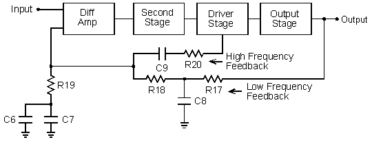
| Figure 1. Amplifier block diagram showing feedback network. |
Figure 1 shows a block diagram of the amplifier with the feedback network connected to it. At audio frequencies, the parallel combination of C6 and C7 is a short circuit while C8 and C9 are open circuits. Feedback is taken from the loudspeaker output through R17 and R18 to the inverting input of the diff amps. The fraction of the output voltage fed back to the diff amp is R19/(R17 + R18 + R19). The gain of the amplifier is approximately equal to the reciprocal of this ratio, which is 21 (26.4 dB) for the values specified.
 |
| Figure 1. Amplifier block diagram showing feedback network. |
At frequencies above about 150 kHz, C8 and C9 become short circuits. This causes the feedback to be taken from the driver stage instead of from the output. By splitting the feedback into two paths in this way, stability from hgh-frequency oscillations that can be induced by load capacitance is improved. Below 1 Hz, C6 and C7 become open circuits causing the amplifier to have 100% feedback at dc. This improves the stability of the bias currents and voltages. With 100% dc feedback, the dc gain of the amplifier is unity.
C6 is an electrolytic capacitor. C7 is a film capacitor which is used in parallel with C6 to improve its high-frequency characteristics. The circuit board layout provides an option to use two polar capacitors in series for C6 or a single non-polar capacitor. If a non-polar capacitor is used, a short circuit jumper must be installed to complete the circuit. One builder who accidentally left the jumper off was distressed because his amplifier had very poor bass response. Without the jumper, the lower cutoff frequency is 1.4 kHz rather than below 1 Hz.
This page is not a publication of the Georgia Institute of Technology and the Georgia Institute of Technology has not edited or examined the content. The author of this page is solely responsible for the content.