The Protection Circuit
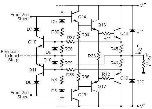
 Figure 1 shows a simplified version of the driver and output stages with the protection circuit added. Only two of the output transistors are shown. Q10 monitors the voltage across R45 and Q11 monitors the voltage across R46. Normally, these transistors are cut off. Excessive currents in R45 or R46 will cause Q10 and Q11 to cut on. This removes drive signal from the bases of Q14 and Q15 to limit the maximum current in Q18 and Q19. R28 through R31, R37, and R38 set the current limit threshold which is a function of both the load voltage and the load current.
 |
| Figure 1. Simplified driver/output stage with protection circuit. |
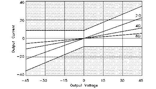
 Figure 2 illustrates the the operation of the protection circuit. The figure shows the amplifier output current versus output voltage. The unshaded region is the region in which the limiter circuit does not activate. The current at which the circuit limits is determined by the output voltage. The figure shows load lines for load resistances of 2, 4, and 8 ohms, all of which stay inside the unshaded region. The graphs in the figure are based on theoretical equations which require estimation of the threshold voltages at which the transistors and diodes in the circuit turn on.
 |
| Figure 2. Operating range of the VI limiter. |
 To prevent the current limit function from operating on fast transients, capacitors can be added in parallel with R28 and R29. To suppress parasitic oscillations in the protection circuit, capacitors can be added in parallel with R37 and R38. With all four output transistors, separate resistors connect from the emitter of each to the bases of the protection circuit transistors. In a previous version of the amplifier, I had a capacitor in parallel with each of these resistors. However, one amplifier built by a student had a strange problem with the protection circuit that we eliminated by removing two of these capacitors. I never really understood this. The full circuit diagram shows only two capacitors.
 D5 through D10 are signal steering diodes. These diodes must be either fast switching diodes or fast recovery rectifiers. If they are not, the protection circuits can be activated on zero crossings of the ac output voltage to cause what looks like crossover distortion on the waveform. D11 and D12 protect Q18 through Q20 from voltage transients which can be induced at the output by inductive loads if the amplifier is driven into clipping. These diodes are normally reverse biased and have no effect on the operation of the amplifier. I once had a student who put D11 and D12 on the circuit boards backwards. In this case, there is a direct short circuit between the positive and negative power supplies, and the amplifier will smoke. The power supply traces were blown off his circuit board.
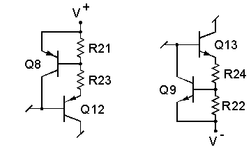
 When the protection circuit is activated, either Q10 or Q11 can saturate. This connects the collector of Q12 or Q13 directly to the loudspeaker output. To protect Q12 and Q13, their maximum current must be limited. This is accomplished by and Q8 and Q9 shown in Figure 3. Excessive currents through R21 and R22 will cause Q8 and Q9 to cut on. This removes the drive signal from the bases of Q12 and Q13 to limit their maximum current.
 |
| Figure 3. Current limiters for Q12 and Q13. |
 I have had people ask me about omitting the protection circuits from the amplifier. Although I don't recommend this, it can be done by omitting Q8 - Q11, R28 - R31, R37 - R40, C17 - C20, and D5 - D8. A fast blow fuse should then be added in series with the output. I recommend a 3 to 5 A fuse. If you wish to remove the rotection circuit from an amplifier that has it installed, all you need to remove is Q10 and Q11.
 I once had a student who omitted the protection circuit from his amplifier. One channel would periodically go dead. He would bring the amplifier into the lab and we would find a fuse blown and nothing else wrong with it. I suspected that one of the bias diodes (D1 - D4) was cracked and was intermittently becoming an open circuit. The student noticed one night that the amplifier went dead when he sat on his bed. Upon investigation, he found the loudspeaker wire for one channel went under the carpet and under a bed post. The weight of the bed had broken the insulation on the wire and he had an intermittent short circuit on the amplifier output. He was lucky that he only blew a fuse because power transistors usually blow faster than fuses. If he had put the protection circuit in the amplifier, he would not have blown the fuse.
 Another student, who built a higher power version of the amplifier, had an interesting experience with the protection circuit in it. This amplifier was the "Double Barrelled Amplifier", which I also published in Audio magazine. The student let his fraternity use the amplifier in their chapter room until he graduated. He told me that the amplifier had been in use for some time when he noticed a some distortion. He investigated behind the amplifier and discovered that the loudspeaker wires were intermittently touching on one channel. He said it had probably been that way for some time because the current had almost eaten through the wires, and they were fairly heavy gauge cables. If he had not put the protection circuit on his amplifier, he could have lost some expensive output transistors.
This page is not a publication of the Georgia Institute of Technology and the Georgia Institute of Technology has not edited or examined the content. The author of this page is solely responsible for the content.
 Figure 1 shows a simplified version of the driver and output stages with the protection circuit added. Only two of the output transistors are shown. Q10 monitors the voltage across R45 and Q11 monitors the voltage across R46. Normally, these transistors are cut off. Excessive currents in R45 or R46 will cause Q10 and Q11 to cut on. This removes drive signal from the bases of Q14 and Q15 to limit the maximum current in Q18 and Q19. R28 through R31, R37, and R38 set the current limit threshold which is a function of both the load voltage and the load current.

